Ceramic Laser Phosphor Converters
For dynamic ceramic converter solutions we offer yellow and green phosphor material with following material properties:
| Yellow |
Green |
|
|---|---|---|
| Phosphor conversion efficacy (lm/W) | 325 ± 15 | 330 ± 20 |
| Emission color coordinates (cx) | 0.417 ± 0.005 | 0.337 ± 0.005 |
| Emission color coordinates (cy) | 0.560 ± 0.005 | 0.591 ± 0.005 |
| Thermal quenching stability @ 170°C | > 89% | > 92% |
| Temperature damage threshold | > 250°C | > 250°C |
| Thermal conductivity in temp. range from 25°C to 200°C (W/m-K) | 5-10 | data on request |
Our dynamic solutions are available in different geometries:
| OD88 | OD64 | OD49 | OD35 | |
|---|---|---|---|---|
| Outer diameter (mm) | 88 | 64 | 49 | 35 |
| Inner diameter (mm) | 74 | 50 | 35 | 25 |
| Thickness (mm) | 0.2 | 0.2 | 0.2 | 0.2 |
| Shape O ring | Available | Available | Available | Available |
| Shape C ring (angle) | 300°/310° | 300°/310° | 300°/310° | 300°/310° |
| Shape Segment | On demand | On demand | On demand | On demand |
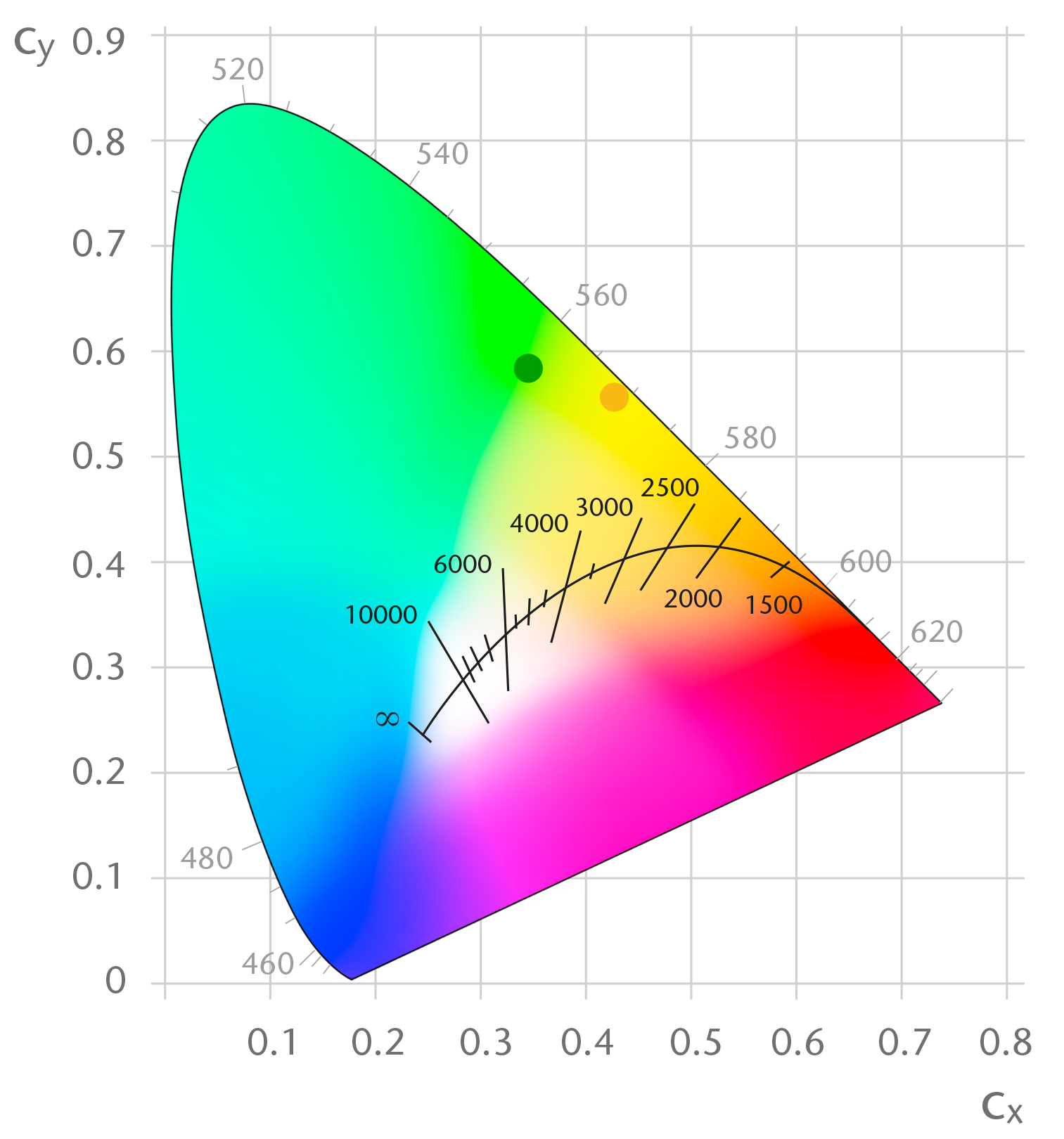
SCHOTT offers a range of dynamic solutions with different emission colors. Details of emission color coordinates can be find on the datasheet in the download section or in the graphic below:
Color coordinates of yellow and green Ceramic Converter material in the 1931/2° color space.
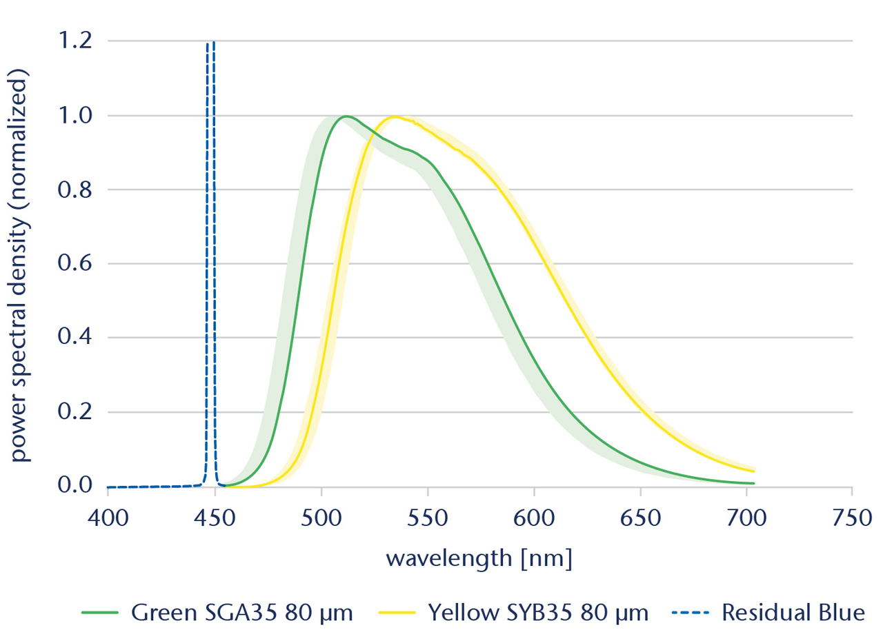
Emission spectrum of yellow and green converter material.
Static Solutions for Digital Projection
Our static solutions are available in following geometries:
Heat spreader dimension (W x L x T in mm)
- 20 x 20 x 4
Phosphor material dimension (W x L x T in mm)
- 4 x 4 x 0.150
- 4 x 4 x 0.100
Customized formats and detailed drawings are possible on request.
For static ceramic converter solutions suitable for digital projection we offer yellow and green phosphor material with following material properties:
| Yellow, 80 µm die thickness | Yellow SYA35 | Yellow SYB35 | Yellow SWA40 |
|---|---|---|---|
| Phosphor conversion efficacy (lm/W) |
> 240 | > 250 | > 200 |
| Phosphor conversion efficiency (W/W) |
> 50% | > 52% | > 42% |
| Emission color coordinates (cx) | 0.411 ± 0.01 | 0.417 ± 0.01 | 0.409 ± 0.01 |
| Emission color coordinates (cy) - Typical value | 0.561 ± 0.01 | 0.557 ± 0.01 | 0.559 ± 0.01 |
| Green, 80 µm die thickness | Green SGA35 | Green SGB35 | Green SGF35 | Shifted Green GGB35 |
|---|---|---|---|---|
| Phosphor conversion efficacy (lm/W) |
> 280 | > 270 | > 240 | > 260 |
| Phosphor conversion efficiency (W/W) |
> 59% | > 57% | > 51% | > 57% |
| Emission color coordinates (cx) | 0.333 ± 0.01 | 0.326 ± 0.01 | 0.320 ± 0.01 | 0.299 ± 0.01 |
| Emission color coordinates (cy) - Typical value | 0.590 ± 0.01 | 0.587 ± 0.01 | 0.583 ± 0.01 | 0.579 ± 0.01 |
| 100 µm die thickness | Yellow SYB35 | Green SGA35 |
|---|---|---|
| Phosphor conversion efficacy (lm/W) |
> 280 | > 280 |
| Emission color coordinates (cx) | 0.417 ± 0.01 | 0.333 ± 0.01 |
| Emission color coordinates (cy) | 0.557 ± 0.01 | 0.590 ± 0.01 * |
| Irradiance limit (W/mm2) - Typical value | 50 | 50 |
- Emission spectrum defined by the power spectral density > 465 nm.
- Efficacy and efficiency specified for emission spectrum.
- AR coating optimized for blue light normal incidence.
- Efficacy, efficiency and color coordinates measured with 60° incident angle of blue laser (449.5 nm) at low laser power.
- Emission is detected in normal direction.
More data and detailed information are available in the brochure in the download section.
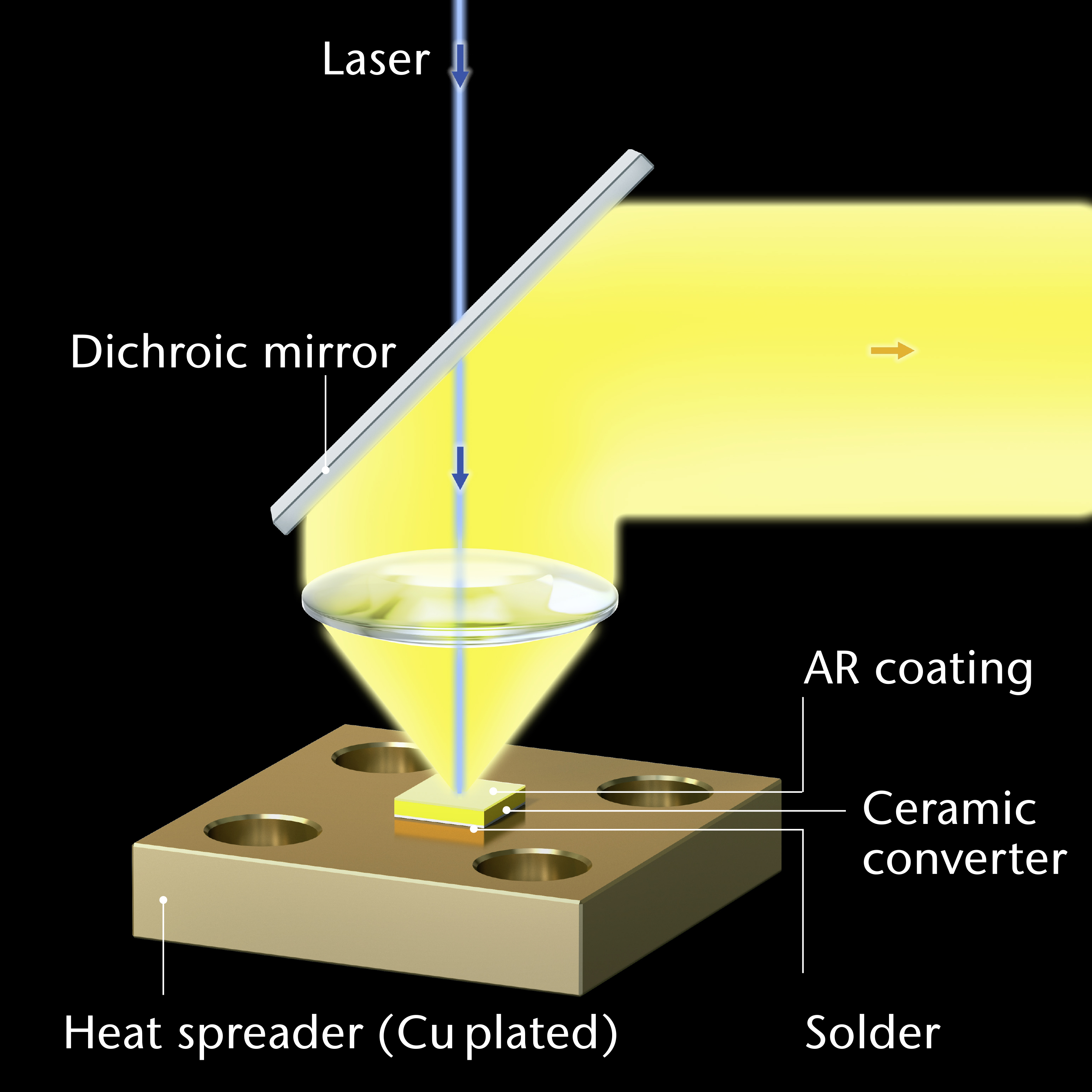
How does this solution work for green or yellow light?
Emission spectrum
Notes:
- Range shows different materials, including GGB35 80 μm, SGF35 80 μm, SGB35 80 μm, SGA35 80 μm, SWA40 80 μm, SYA35 80 μm, SWD50 80 μm, SYB35 80 μm and others
- Details can be provided upon request
Irradiance limit
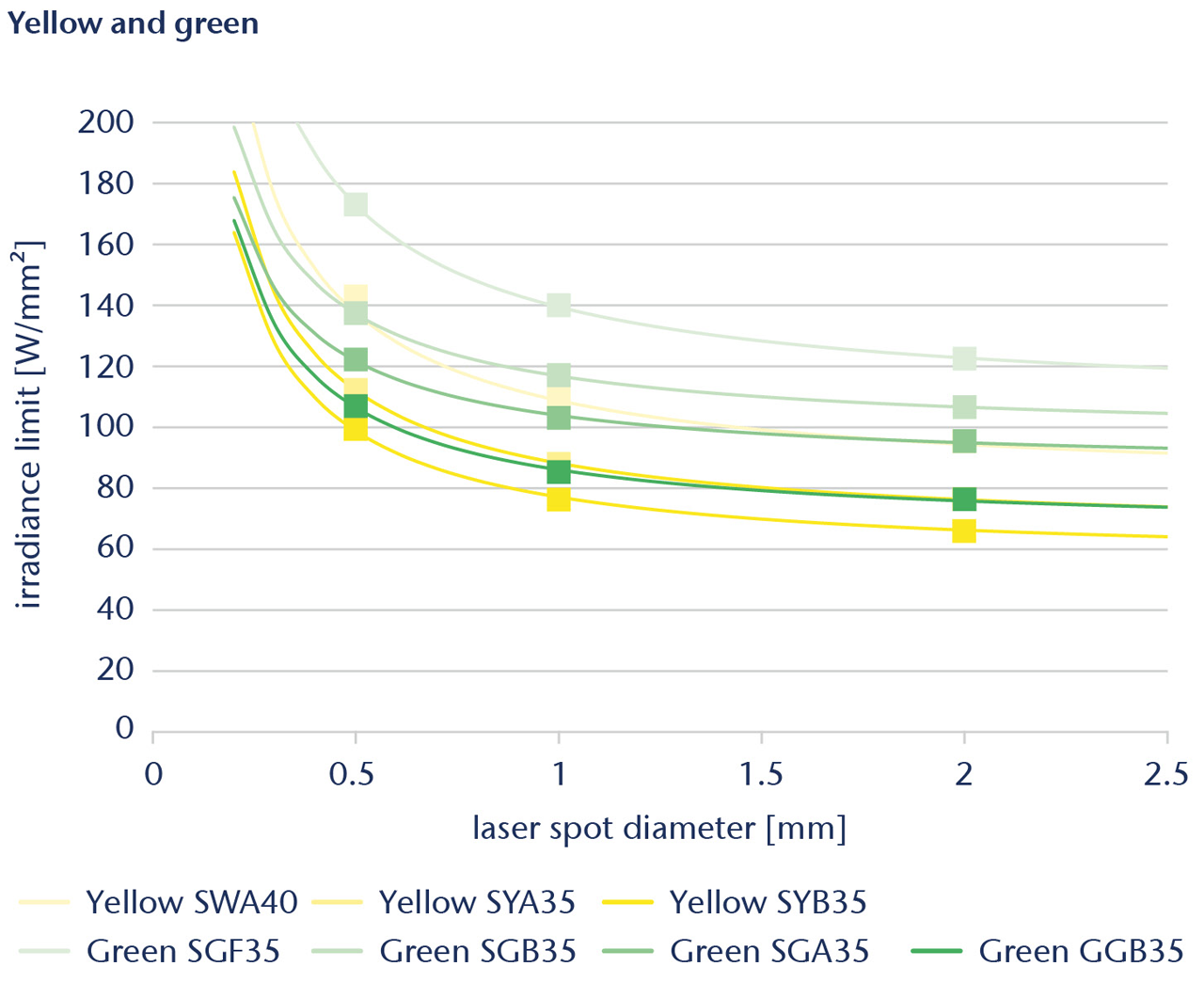
Notes:
- Indicated irradiance limits are not based on measurements, but on validated numerical simulation, taking into account all properties of relevance.
- The values apply for illumination by a 450 nm CW mode laser with tophat profile, and for good thermal contact of a heatspreader sized 20 x 20 x 4 to a heatsink at 30 °C.
- For safety reasons stay at least 20 % below indicated irradiance limit. Accordingly, the values on this page may in no case be understood as technical product specifications, and are for general orientation purposes, only.
The blue laser light applied via a dichroic mirror blocks residual blue light, that is reflected from the sample.
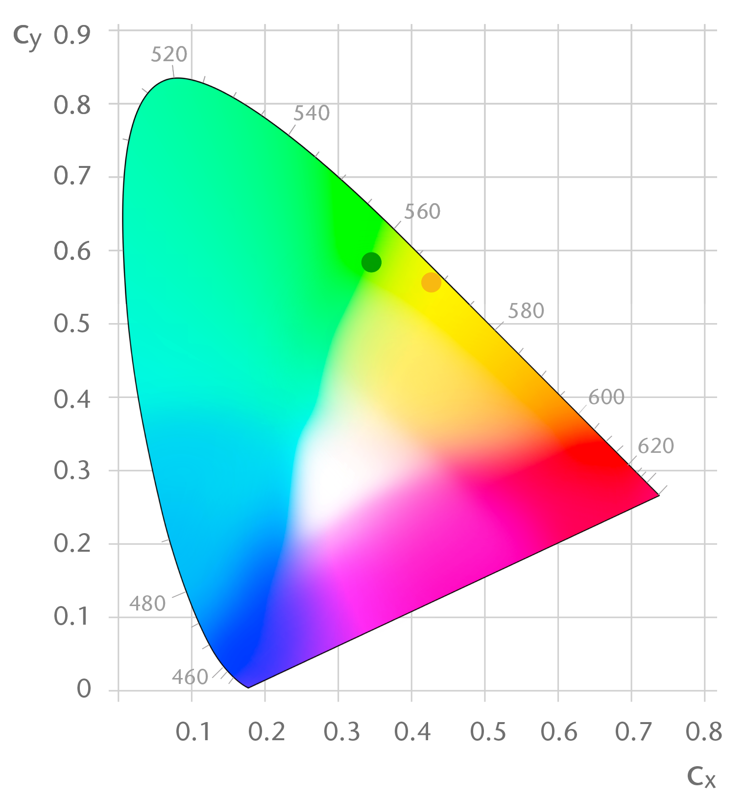
Color coordinates of green and yellow ceramic converter material in the CIE 1931/2° color space.
Static Solutions for Illumination
Our static solutions are available in following geometries:
Heat spreader dimension (W x L x T in mm)
- 20 x 20 x 4
Phosphor material dimension (W x L x T in mm)
- 4 x 4 x 0.150
Customized formats are possible on request.
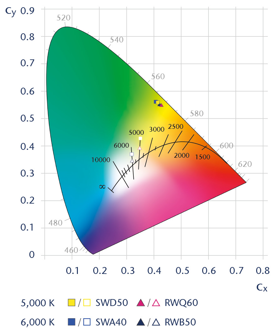
White light is the next generation of design. We offer three types of white static converter materials for correlated color temperatures (CCT) of 6,000 K and 5,000 K each to suit a wide range of applications.
White 6,000 K
| 150 µm die thickness | White SWA40 | White RWA45 | White RWB50 |
|---|---|---|---|
| Phosphor conversion efficacy (lm/W) |
> 230 | > 225 | > 220 |
| Phosphor conversion efficiency (W/W) |
> 63% | > 62% | > 62% |
| Emission color coordinates (cx) | 0.4100 ± 0.007 | 0.4170 ± 0.007 | 0.4233 ± 0.007 |
| Emission color coordinates (cy) | 0.5603 ± 0.007 | 0.5555 ± 0.007 | 0.5514 ± 0.007 |
| White color coordinates (cx) | 0.3198 | 0.3205 | 0.3212 |
| White color coordinates (cy) | 0.3655 | 0.3546 | 0.3454 |
| Emission color coordinates (u’) | 0.18420 | 0.188886 | 0.19306 |
| Emission color coordinates (v’) | 0.56637 | 0.56607 | 0.56585 |
| White color coordinates (u’) | 0.18961 | 0.19383 | 0.19759 |
| White color coordinates (v’) | 0.48759 | 0.48251 | 0.47807 |
White 5,000 K
| 150 µm die thickness | White SWD50 | White RWP55 | White RWQ60 |
|---|---|---|---|
| Phosphor conversion efficacy (lm/W) |
> 240 | > 235 | > 230 |
| Phosphor conversion efficiency (W/W) |
> 62% | > 61% | > 61% |
| Emission color coordinates (cx) | 0.4142 ± 0.007 | 0.4229 ± 0.007 | 0.4287 ± 0.007 |
| Emission color coordinates (cy) | 0.5598 ± 0.007 | 0.5533 ± 0.007 | 0.5490 ± 0.007 |
| White color coordinates (cx) | 0.3520 | 0.3500 | 0.3488 |
| White color coordinates (cy) | 0.4286 | 0.4063 | 0.3926 |
| Emission color coordinates (u’) | 0.18640 | 0.19237 | 0.19642 |
| Emission color coordinates (v’) | 0.56677 | 0.56627 | 0.56594 |
| White color coordinates (u’) | 0.18930 | 0.19512 | 0.19895 |
| White color coordinates (v’) | 0.51851 | 0.50961 | 0.50378 |
Tolerance window for white color coordinates (cx;cy) / (u’;v’) for download in the download section.
Notes:
- White color coordinates change with blue laser wavelength and are measured at 449.5 nm.
- Emission spectrum is defined by the power spectral density > 465 nm.
- Efficacy and efficiency is measured for full (white) spectrum, defined by the power spectral density > 400 nm.
- AR coating optimized for blue light incident angle of 60°.
- Efficacy, efficiency and color coordinates measured with 60° incident angle of blue laser at low laser power.
- Emission is detected in normal direction.
More data and detailed information are also available in the brochure in the download section.
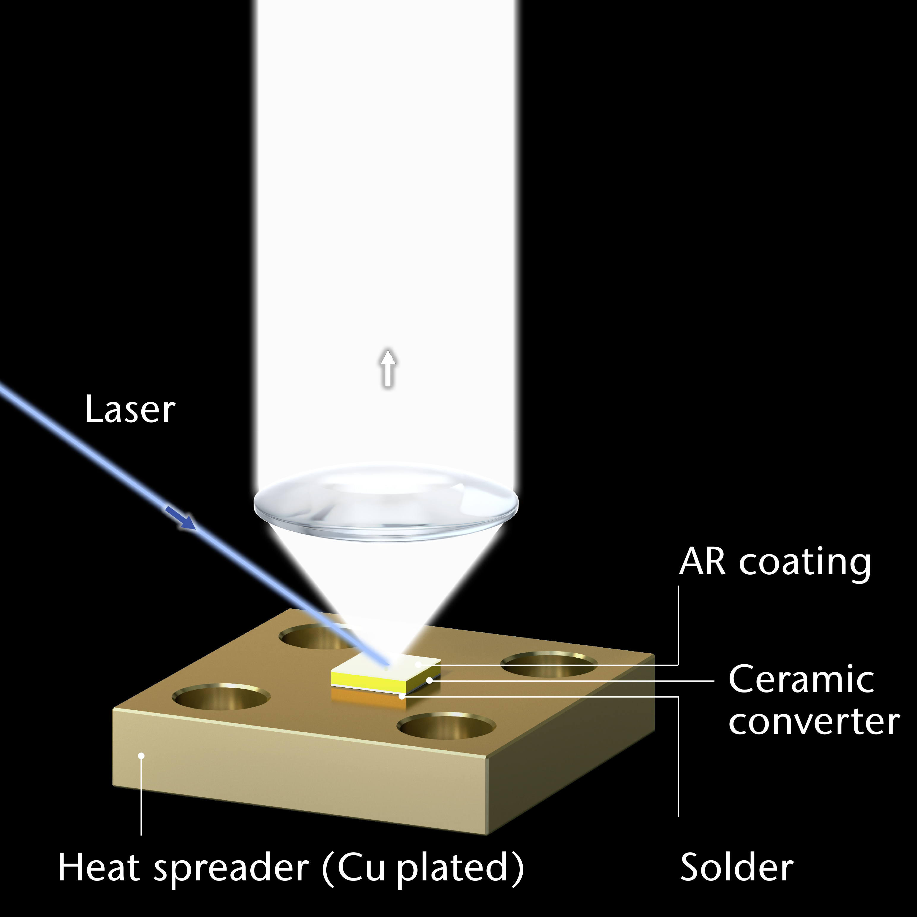
How does this solution work for white light?
Emission spectrum
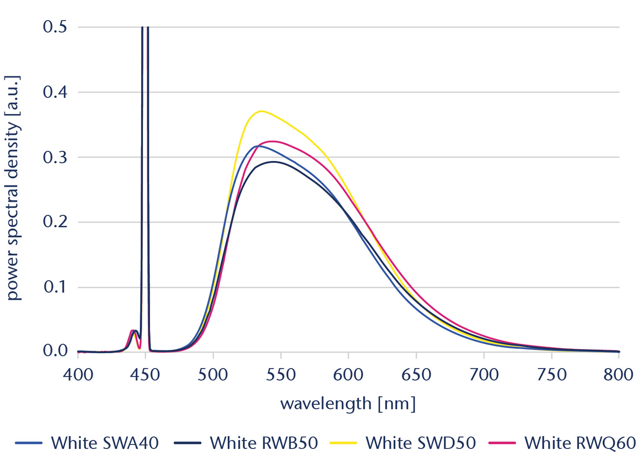
Irradiance limit
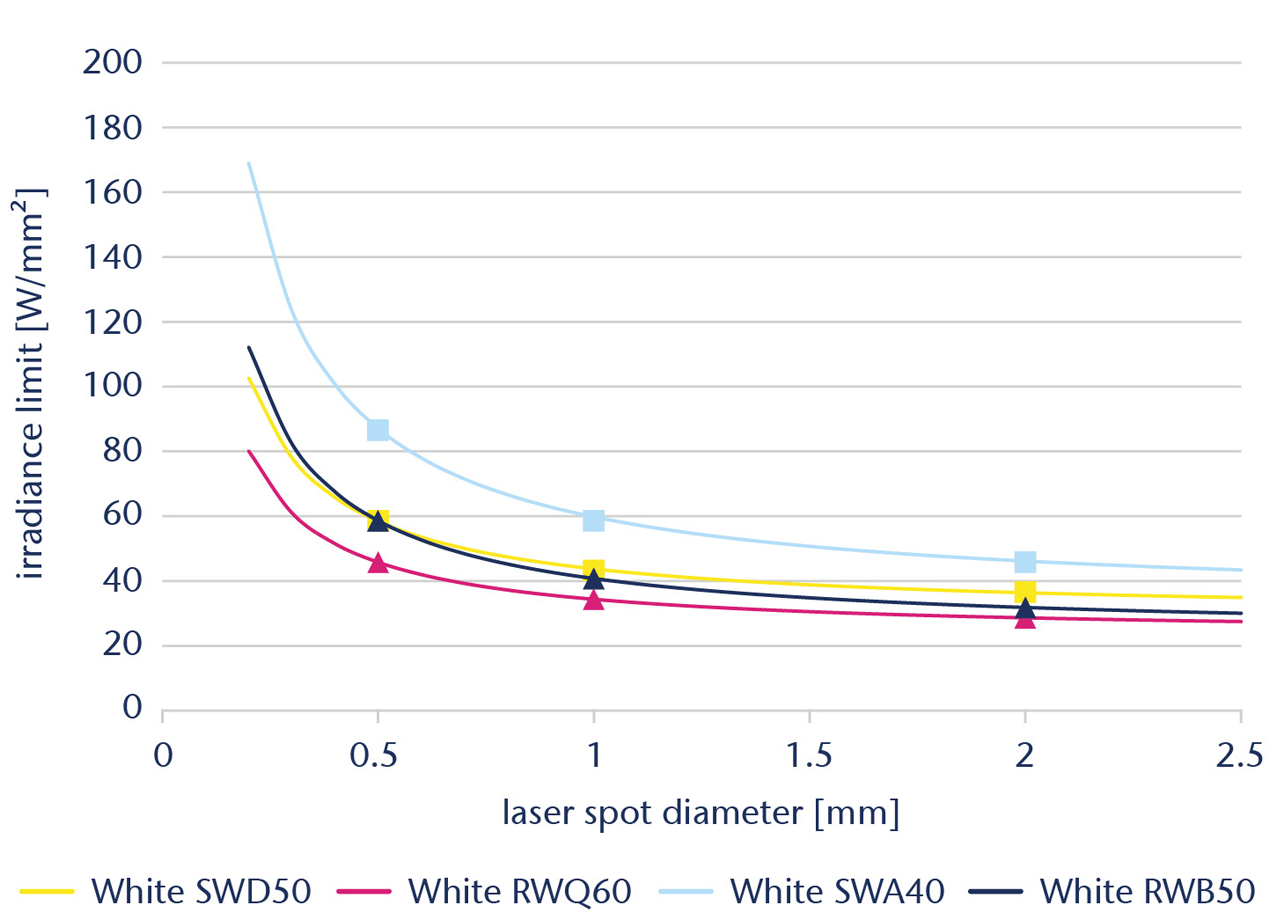
Notes:
- Indicated irradiance limits are not based on measurements, but on validated numerical simulation, taking into account all properties of relevance.
- The values apply for illumination by a 450 nm CW mode laser with tophat profile, and for good thermal contact of a heatspreader sized 20 x 20 x 4 to a heatsink at 30 °C.
- For safety reasons stay at least 20 % below indicated irradiance limit. Accordingly, the values on this page may in no case be understood as technical product specifications, and are for general orientation purposes, only.
To meet the desired color coordinates, the material is designed for diffuse reflection of just the right portion of blue light.
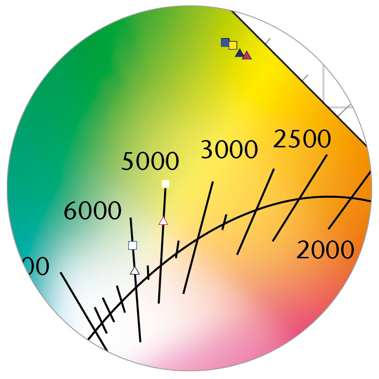
Color coordinates of white ceramic converter material in the CIE 1931/2° color space.